Integrated Sewage Treatment Machine
Product IntroductionIntegrated sewage treatment machine is a set of products combined in one system that meets the requirements for sewage pre-treatme...
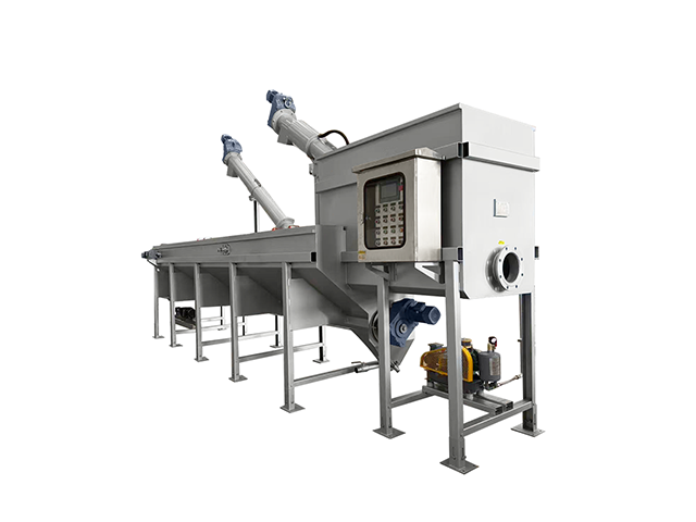
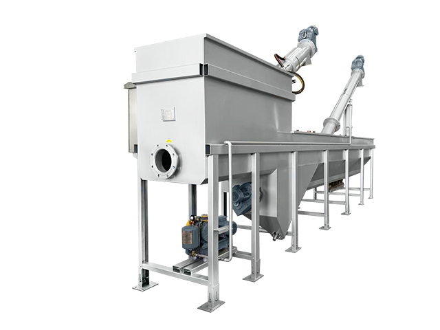
Product Introduction
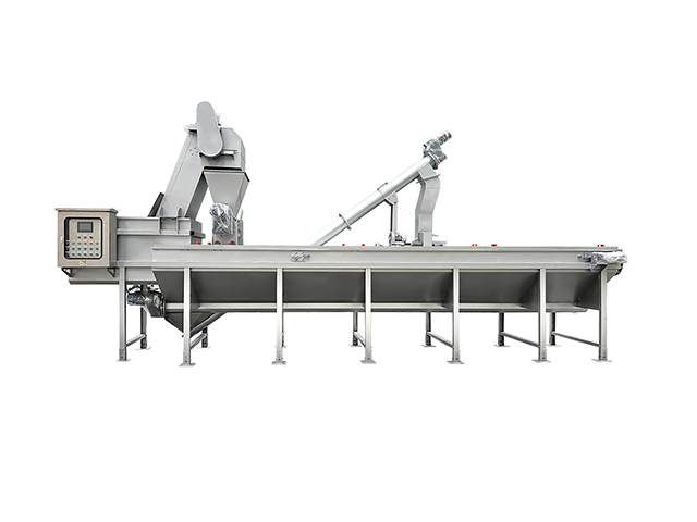
Integrated sewage treatment machine is a set of products combined in one system that meets the requirements for sewage pre-treatment of wastewater.
The equipment captures the materials at the grid and dewaters them in a press. Sand settles in the longitudinal sand trap and is then removed by screw conveyor.
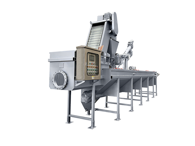
The housing is available for outdoor installation and the places with below-zero temperatures.
Individual functions and their sequence are controlled by the control panel and PLC.
The equipment features a small footprint and allows for quick installation on a concrete slab.
The unit can be used in wastewater treatment plants with smaller flow rate where it can substitute a sequence of devices, such as grid, press, aeration equipment, fat collection equipment, screw conveyor and sand catcher. Putting all of these devices in a single container saves built-up area, costs of construction and time of realization. Therefore, integrated sewage treatment machine is most suitable for re-construction works of WWTPs.
The product has the following features:
1. Integrated structure: integrates filtering, sand settling, sand removal, oil removal and slag removal functions. Easy to manage and save land.
2. All parts in contact with sewage are made of 304 stainless steel, which guarantees absolute corrosion resistance and long service life.
3. Easy installation and time-saving.
4. Installed on a flat concrete foundation or in a foundation ditch.
Working Principle
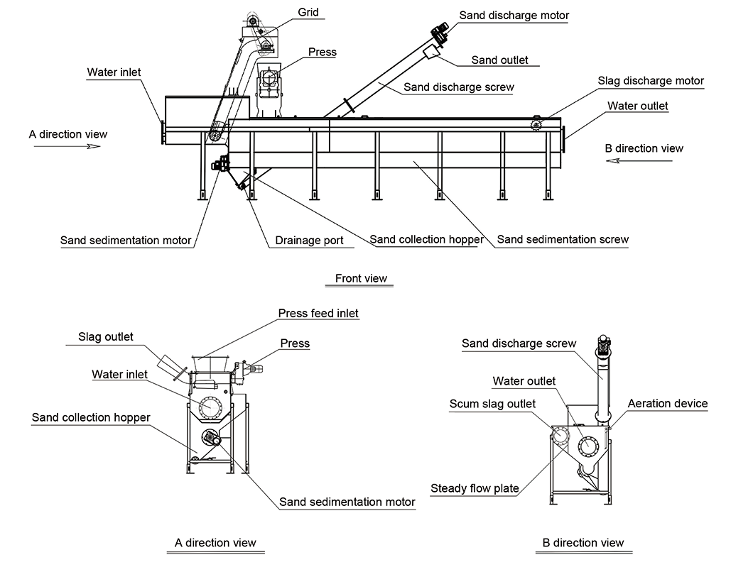
1. First, the sewage will be fed into the equipment, the suspended solids in the sewage are filtered and intercepted by the grid machine. The structure of the gird machine is flexible and varied, including spiral type, drum type, rake filter belt type, bar type, perforated plate type, ladder type, etc.
2. The intercepted slag will be lifted up and falls into the press machine. The slag will be squeezed and dehydrated, and then discharged.
3. The squeezed filtrate flows back to the sand box through a plastic hose.
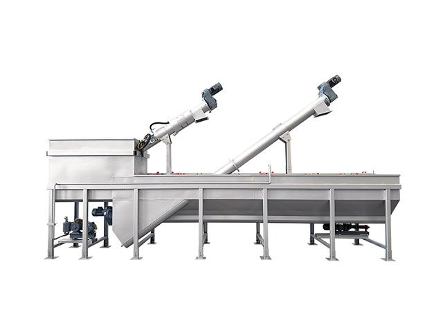
4. As the sewage continues to flow backward, the sand in the sewage settles in the groove of the sand discharge screw.
5. The sand sedimentation screw transports the sand in the opposite direction of the water flow, and finally concentrates the sand to the sand collection box.
6. The inclined sand lifting screw transports the sand in the sand collection box upwards. During the transportation process, the sand is separated from the sewage and discharged.
7. Finally, the treated sewage will be discharged from the outlet and flows to the next level sewage treatment system.
8. In addition, the aeration device can be started simultaneously during operation to wash the fine sand in the sewage.
9. Under the action of aeration, the washed dirt will be pushed to the scraping area, and then scraped off by the scraper.
Technological Process
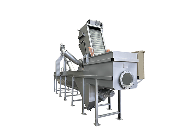
The wastewater flows through the inlet branch and then flows through the self-cleaning grid into the longitudinal sand chamber. There the sand is separated and goes down in the inclined walls to the bottom where a shaftless screw is installed. The sand is transported in intervals to a cistern from which it is further transported by screw conveyor to a container.
The area of sand chamber can be aerated, so that the separation of sand from organic particles and ballast materials is more effective. Flowing small particles of indissoluble substances and fats can be either entrapped by a downflow baffle when floating on water level or they go past an overflow plate into the outlet branch. Entrapped substances and fats are collected by a chute and transported to a fat accumulation tank. They are then pumped back in front of the self-cleaning grid.
The whole process is fully automatic and controlled by a scheduled program with a level base control. The control cabinet also enables manual operation which is suitable when visually inspecting the quantity of fats entrapped by downflow baffle.
Application Areas
1. Municipal wastewater.
2. Chemical wastewater.
3. Industrial wastewater.
4. Food wastewater.
5. Other solid-liquid separation areas.
Technical Parameters
Model | Capacity (m3/h) | Total power (kW) | Weight (kg) | Dimensions (mm) |
MWT-50 | 50 | 4.07 | 1500 | 4500*1900*3770 |
MWT-100 | 100 | 5.17 | 2200 | 5500*2262*3770 |
MWT-200 | 200 | 5.17 | 2600 | 7500*2262*3770 |
MWT-270 | 270 | 5.17 | 2850 | 8350*2262*3770 |
MWT-450 | 450 | 6.27 | 3350 | 10000*2362*3770 |
MWT-500 | 500 | 6.27 | 3600 | 11000*2362*3770 |

CATEGORIES
LATEST NEWS
- Industry News And Technical Support
Analysis of Main Faults of Disc Separator
- Industry News And Technical Support
Analysis and Treatment of Electrical Faults of Centrifuge
- Industry News And Technical Support
Suggestions For Centrifuge Selection
- Industry News And Technical Support
Application of Horizontal Decanter Centrifuge in Chemical Wastewater Treatment (2)
CONTACT US
Contact: Bryan Wu
Phone: +86-15995396766
Tel: +86-15995396766
Email: m15995396766@gmail.com
Add: NO.198 JUNMA ROAD, QITING STREET, YIXING, JIANGSU, CHINA.